|
|
Goped & Scooter-TuningRacing exhaust
Racing carburetors Racing cylinders Tuning and more... Product searchInfo
Gas Scooter
Blata Vehicles California Goped + General information + Videos/photos + Exploded drawings + Tuning/mounting guide + Chain/sprockets + Conversion inch/mm Chung Yang / Zenoah Pocket Bike NewsletterDownloads |
California Goped -
|
|||||||||||||

 |
|
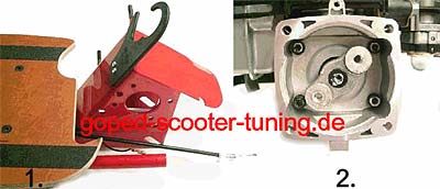
| Step 1 They dismantle the tank (three screws) of the Goped. Then from the tank side by the frame the engine from the frame (four screws). |
Step 2 Mounting the clutch case (four screws) and then the clutch holder (one screw). |
 |
|
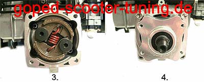
| Step 3 They can fit the clutch with two black screws at the outside and the plain washers as well between clutch and clutch holder. |
Step 4 They are putting the clutch bell on the clutch case with four screws, the plain washers and blowing up rings, together now. |
 |
|
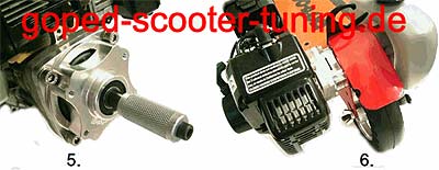
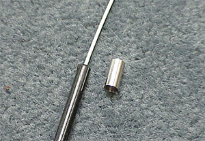
| Step 5 You can mount a drive spindle at the clutch case now. |
Step 6 Mounting first the engine on the frame and after that the tank on the frame. |
up
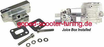
Go-ped Sound Suppressor/Spark Arrestor
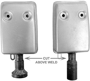
Installations Instructions Installation of the Go-ped Sound & Spark Suppressor is a simple task when following the Installation steps in this pamphlet. The sound and spark suppressor is a simple but effective devise. When installed correctly to your Go-ped product. First, you must remove any extension tube that may be coming off the end of the motors muffler system. If your muffler is already equipped with a spark suppressor, you will need to cut that part off the muffler just above the weld to fit the Sound & Spark Suppressor on the exhaust outlet of your motor.
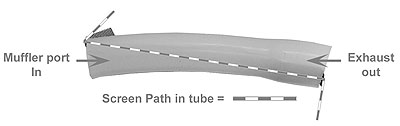
Once your are ready to install the Sound & Spark Suppressor you will need to make sure the internal metal screen is orientated correctly. You will notice the high temperature silicon tube has two different ends with part of the screen sticking our on both ends. The small diameter side is where the engine exhaust will exit from. Take note of the location of the screen. The lager inside diameter will attach to the muffler of you engine. The screen must be orientated so that it is opposite the screen sticking out on the outlet side of the tube (it does not go in inside the muffler) sp sparks that are carried with the exhaust will be trapped by the internal screen.
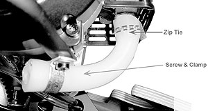
With the Sound and Spark suppressor now attached to the muffler, you can now install the Zio Tie, clam and screw. The screw and clam will attach to the visible mounting location on the body of the motor below the Go-ped.
up
Installing your new ESR750 Seat Kit on your Go-ped
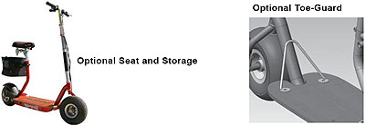
Installation of your seat is simple, but proper installation is critical for safety. Begin by inspecting your seat. There should be a rubber pad glued to the rectangular “foot” which will rest on the motor. There should also be a nut and bolt which will be used to clamp the seat to the scooter. If the hardware is installed in the seat frame, remove it at this time. Working from the rear of the scooter, slide the “clamp” over the tail of the frame. You will need to maneuver the seat frame around the fender. Slide the clamp onto the frame until the clamp bumps into the axle bushing and cannot be pushed on further. Now rotate the frame down until the rubber foot is resting on top of the motor tube. Now install the bolt and nut through the bushings on the seat clamp. (They are down next to the rear wheel.) Tighten them up securely. Check to make sure your seat is securely installed. You should be able to lift up the scooter by the seat, without the seat frame moving. If the seat frame rotates, retighten the nut and bolt. Set the seat to a comfortable height and tighten the seat post clamp. Proper seat height adjustment should allow the rider to firmly rest both feet on the ground while standing over the seat. To prevent your feet from interfering with the steering of the scooter while using the seat option, it is required that you install the “Toe-Guard”. Remove the front two deck screws with a T30 Torx tool. Place the toe guard on the deck, so that it leans forward, away from the seat. Securely install the two button head bolts through the toe guard and down into the ESR frame. Install the (2) provided ¼-20 x 3/4” button head cap screws.
ATTENTION: When riding your ESR750 with the seat attachment it is recommended that only ECONO Mode be used for safety.
WARNING: You should not operate you scooter with the seat attachment without the use of the Toe-Guard. Your feet could get in the way of the steering causing a loss of control of your Go-ped scooter.
up
Go-ped ESR750 / ESR750EX Rear Brake Installation Instructions
This kit provides all the parts you need to install a rear brake on your ESR750 or ESR750EX. It will not work on an ESR Sport, or other Go-ped scooter. Installation of this kit requires good mechanical skills. Please review these instructions completely before beginning. If you are uncomfortable with any of the steps required please consult an approved Go-ped dealer for professional installation. Failure to properly install the rear brake could result in loss of control of the scooter, and injury.
Tools Needed:
1) Torx #T30 screwdriver (to remove deck)
2) Drill with ¼” drill bit
3) 2.5mm allen wrench
4) 3mm allen wrench
5) 5mm allen wrench
6) two 15/16” wrenches
7) 9/16” wrench and 9/16” socket
8) Philips screwdriver
Parts List:
(1) Large aluminum bracket
(1) Small aluminum bracket
(1) ESR Fender - modified
(4) M4x0.7 x12mm Flat Head Screws
(1) Maddog brake caliper
(2) M6x50 SHCS
(1) Steel Tube; 3/8"x .058"x .85"
(8) Small washers
(2) Axle Washer; 1"x .641"x .060
(1) Axle Bolt; 5/8-18x8.5
(1) Aluminum Spacer; 7/8" OD x .755" long
(1) Right brake lever
(1) Brake cable; 68"Housingf / 82"Cable
(1) Bolt; M6 x 22 Socket Head w/patch
(1) Crimp-on Brake cable end
(1) Brake cable ferrule
(4) Large zip ties
(4) Small zip ties
(1) Brake disc
(4) Aluminum Spacer; sprocket to disc
(4) Low head 3/8”-24 hex bolts
Instructions:
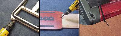
- Remove deck
- Drill 1/4” to 3/8” hole in pan as shown
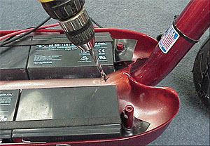
- Drill hole through deck
- For the regular ESR750 model, drill through the deck as shown. Drill the hole about 5” from the right edge of the deck, so that the hole is NOT directly above the charger.
- For the EX model, drill through the 1” thick spacer deck as shown. Don’t drill the top deck.
- Remove the right hand grip.
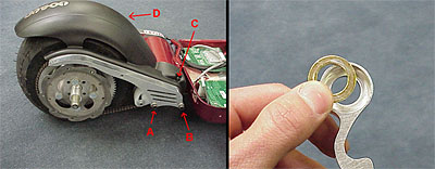
- Now you have a choice. For proper installation, the electronic throttle should be temporarily removed from the T-bar, so that the new brake lever may be installed on the inside of the throttle. However, for easier installation, the new brake lever may be installed on the outside of the throttle. If you choose this easier installation, you simply need to slide the throttle towards the center of the T-bar by about ½”. The proper “inside” position requires a few steps: a. You will need more slack in the electrical wire in order to get the throttle off the end of the T-bar. Fold the t-bar down, and pull the electrical wire up through the reflective T-bar pad. This pad has strong adhesive on the back, which will make it difficult to move the wire. Pull a few inches of wire through the pad to create slack. b. Loosen the small screw which holds the throttle to the T-bar. c. Slide the throttle off the end of the T-bar. d. It is sometime difficult to slide the throttle off. If you have trouble, completely remove the small screw, and then slide the throttle off the T-bar. An aluminum “ring” from the throttle will be left behind on the t-bar. Use a hammer to gently tap the ring off the t-bar, and then reinstall it in the throttle. e. Install the brake lever onto the t-bar, then reinstall the throttle lever.
- Slide the brake cable down through reflector pad, between the two existing cables. It may be helpful to spray some lubricant on the cable housing. One end of the cable has a cylinder on it. That end stays at the top of the t-bar. **For easier installation you may skip this step, and simply zip-tie the new cable to the t-bar, while leaving it outside the reflector pad.
- Pull the brake cable through new hole in pan as shown. You may need to lift the pan a little.
- Remove fender.
- Remove rear wheel.
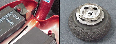
- Deflate rear wheel! This is very important. Failure to deflate the tire before disassembling the rear wheel can crack the wheel!
- Disassemble rear wheel. This requires removing the 4 nuts with a 9/16” socket and wrench.
- Reassemble wheel with the four new bolts, four new spacers, & brake disk. You will reuse your existing wheel, aluminum sprocket, four spacers, and four nuts. As you reassemble the rear wheel you must align sprocket to wheel, to make them as concentric as possible. Failure to do so will make it very difficult to properly tension your chain.
- Install wheel onto frame with new longer axle bolt.
- Slide the old aluminum axle spacer, and also the new ¾” long axle spacer onto the new axle bolt. Those two spacers will be touching each other.
- Assemble the new plastic fender to the new aluminum brackets, using the four 4mm screws. Be careful not to cross thread the screws into the aluminum. Turn the screws in until their heads are almost flush into the plastic. To prevent the screws from loosening, loctite thread locker can be used on the screws.
- Install the new fender and bracket assembly onto the scooter. Do not tighten the bolts up until the end of installation.
- In locations A & B you will install the 50mm (2”) long 6mm socket head screws. Using a washer under the head of each screw.
- In location B you will place the small steel tube on the screw. The tube will be between the new aluminum bracket and the painted frame.
- In both locations A & B you may need to add washers on the screws, BEHIND the new aluminum bracket. Use these washers as shims to get the large bracket into the proper location. You will need to make sure that the plastic fender is not touching the chain. It’s most likely that the fender may want to rub the chain at the rear of the scooter. You may need to use more shim washers in location A than in location B to angle the fender out away from the chain. Don’t try to get this perfect until everything else is installed, including the brake caliper.
- In location C you may reinstall the old screw which was used in this location. You may delete this screw if you have trouble installing it.
- In location D (not shown) reinstall the old Philips head screw which was used in this location.
- Now you will slide the smaller aluminum bracket onto the rear axle. However, you will probably need to install one of the large axle washers between this bracket and the axle spacers. You will use these washers as shims to put the bracket in the correct location. Normally one washer will be used, but it is fine to use zero or two washers as necessary.
- Install the axle nut with a washer behind it. Don’t tighten it down yet, so that you can rotate the small bracket around on the axle.
- Line up the hole on the small bracket with the hole on the large one. Install the M6 x 22mm (7/8” long) socket head screw. Leave it a little loose at first.
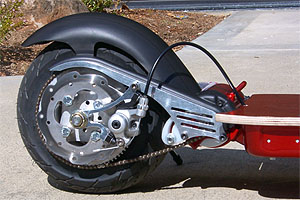
- Now install the brake caliper to the small bracket. If you are unfamiliar with how the Maddog brakes are installed and adjusted, it is recommended that you first carefully examine the caliper in your hand before installing it. Jump ahead a few steps in these instructions and read about all the adjustments the caliper has.
- The brake caliper comes attached to its own bracket, which isn’t used here. When you remove that existing bracket from the caliper, save the screws. Reuse those screws to bolt the caliper to the new aluminum bracket. DON’T tighten the caliper screws yet.
- Now tighten up all the screws and nuts except for the two which hold the brake caliper in place. Don’t over tighten the rear axle nut, or it may cause the rear wheel to not spin freely.
- Check all the alignment.
- Make sure the fender doesn’t rub on the chain.
- Make sure the small bracket doesn’t rub on the heads of the four wheel bolts.
- Flip the scooter over and make sure the chain is running straight. You may need to move the small sprocket on the motor shaft to realign the chain. To do this you must loosen the small set screw in that sprocket with the 2.5mm allen wrench.
- You may need to reset the chain tension by adjusting the plastic chain tensioner. **It’s important to realize that the large sprocket will never be perfectly concentric to the wheel. For that reason, as you rotate the wheel the chain will always have one position which is tighter than the others. Rotate the wheel until you find the tightest spot on the chain, and set the tension with the wheel in that position.
- Now you may align the brake caliper and tighten it into place. The caliper has MANY adjustments on it which allow you to properly align it. Here is an explanation:
- Where the two bolts hold the caliper to the new bracket, you will notice that the holes in the caliper are elongated. That allows you to shift the caliper back and forth to get it into the correct location.
- There is a large black plastic knob on the back of the caliper. Turning that knob clockwise will push in the brake pad on that side of the caliper.
- Directly opposite that black knob there is a small screw which pushes in the other brake pad. The screw is not visible. If you push a small 3mm allen wrench into the hole on the caliper’s lever arm, you will find the screw.
- The caliper and the brake lever both have barrel nuts which are used to take up slack in the cable.
- Now some notes about proper caliper installation:
- Generally speaking you want the caliper pads to be evenly spaced on either side of the disc.
- You don’t want either pad to drag on the disc.
- You will probably want to turn in both of the pads a little using the black knob and the small screw. If you don’t turn the pads in, you may not be able to get the caliper to fully close on the disc, when you pull the brake lever.
- Finally, a recommended procedure:
- Turn in both the knob and the hidden screw so that the pads are close to the width of the brake disc, but still loose.
- With your hand, twist the lever arm on the caliper, so that the caliper clamps onto the disc. This will center the caliper.
- Now tighten the two screws which hold the caliper to the bracket.
- Release the arm, and spin the back wheel. One or both of the pads will probably drag on the disk. Back off the knob or the hidden screw as necessary, until there is no drag.
- You may be done, but you’ll need to check again once the brake cable is hooked up.
- Now route the brake cable through the hole you drilled in the pan, and the hole you drilled in the deck.
- Hook the cable to the new brake lever. There are TWO cable positions on the brake lever. The metal cylinder on the end of the cable should be installed into the position which is FARTHER from the brake lever pivot.
- Slide the chrome brake ferrule onto the caliper end of the brake cable housing. Crimp it lightly in place with a plier or wire cutter.
- Attach the cable to the brake caliper. Make sure all the slack is out of the cable, and tighten the nut on the caliper arm to lock the cable into place.
- Zip tie the brake cable to the neck of the frame, just outside the pan.
- Check the path of the cable through the pan. Make sure it isn’t kinked. Also make sure it’s not laying on top of the electronics. Use zip ties to hold the cable in place if necessary.
- Optional: use a silicone sealant to seal the hole you drilled in the pan. This will help keep the pan sealed.
- Reinstall the deck.
- Make sure the cable is moving freely, and not pinched somewhere.
- Check to make sure the rear brake isn’t dragging. Also check to make sure that pulling the new brake lever fully engages the rear brake. The lever should not move all the way to the grip. Readjust the brake caliper if necessary. You may also use the barrel nuts at the caliper or lever to take up cable slack.
- When the brake is properly adjusted, take the scooter for a careful test ride. Slowly get used to using the rear brake. Make adjustments if necessary. A dragging rear brake will greatly reduce your range.
up
Go-Wagon Assembly instructions
Install the front axle
- The front axle bolts onto the deck using four ¼-20 x1” flat head bolts, four ¼” washers, and four ¼-20 lock nuts.
- The front axle installs where the pocket is cut into the deck. The pocket is there to make clearance for the top of the pivot tube and the weld.
- Because the front axle pivots around, there is no wrong way to install the front pivot. Just line up the four holes on the pivot with the deck and bolt them up.
Install the rear axle on the wagon
- Use four ¼-20 x1” flat head bolts and four ¼-20 lock nuts to install the rear axle.
- The rear axle has no front and back, it can’t be installed backwards.
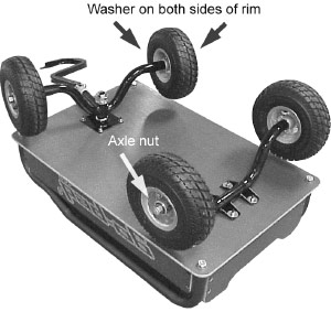
Install the wheels
- Install the four wheels on both axles. Use a standard 5/8” axle washer on both sides of the wheel.
- Install 5/8-11 low nylock nuts on the axle to retain the wheels.
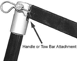
Install a handle or tow bar
- The handle and tow bar install in the same way. The handle and tow bar install into the aluminum hinge fitting using the clevis pin.
- The ½” diameter x 1.5” long clevis pin slides in place and the bent “hairpin” retains it.
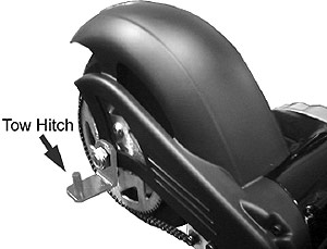
Install tow hitch to Scooter
- The “L” shaped tow hitch installs on your big wheeled Go-Peds rear axle.
- Remove the rear axle nut and washer. Use the “L” shaped tow hitch in place of the washer and re-install the nut.
- The tow bar should slide over the hitch pin and be held in place by the supplied clevis pin.

![]()