|
|
Goped & Scooter-TuningRacing exhaust
Racing carburetors Racing cylinders Tuning and more... Product searchInfo
Gas Scooter
Blata Vehicles + General information + Blata News + Videos/photos + Exploded drawings + Tuning instructions + Chain length California Goped Chung Yang / Zenoah Pocket Bike NewsletterDownloads |
Blata Minibike -
Blata Elite 14 Steering Dumper Instruction |
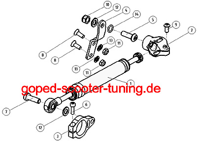
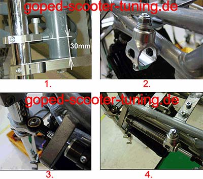
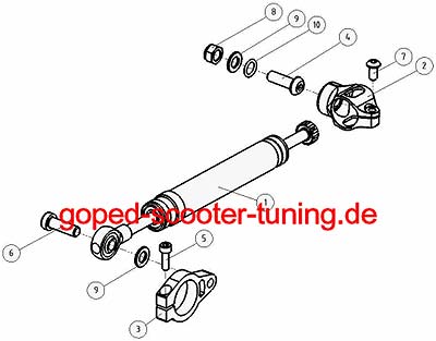
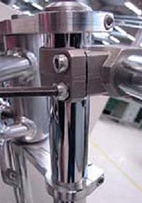
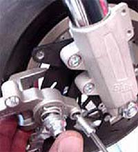
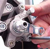
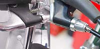
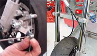
In the first step tighten Body holder of Blata steering dumper – complete (2) to the frame of the midi bike (fig.1). Slide on the Holder of steering dumper (3) on the right fork so the head of the Screw M5 x 16 (5) point in front of the midi bike and the tighten window point in the central point of steering (fig.2). The distance between bottom solid of the Holder of steering dumper (3) and top solid of the bottom crown handle is approximately 37mm (fig.2).Slide the Steering dumper (1) into the Body holder of Blata steering dumper – complete (2) from the front side of the midi bike. By the Screw M8 x 25 (6) tighten Steering dumper (1) inside the Holder of steering dumper (3) (fig.3). When You are turning of the steering to straight direction adjust position the body of the Steering dumper (1) in the Body holder of steering dumper – complete (2) so both of extreme position of the steering wasn’t limited by moving of the piston rod of the steering dumper and by Screw M6 x 12 (7) fix the position the body of the Steering dumper (1) in the Body holder of steering dumper – complete (2 (fig.4). By turning the steering to the both of the extreme position testing, if isn’t part of the Blata Steering dumper (1) in contact with part of the frame of the midi bike (fig.4). 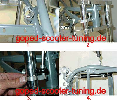 |
up
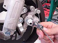 |
Dismantle the front lining. Loosen the cable retainer and dismantle the brake cable. |
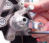 |
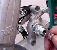
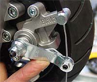
Unscrew the screw 312.018.00 and remove the brake pads and the brake pad spring from the calliper. |
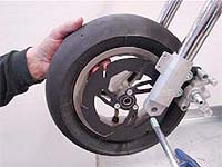 |
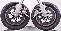
Loosen nuts and pull out the front wheel axle. Then pull the wheel out from the brake caliper in the direction of front forks. |
 |
Remove the brake caliper from the brake holder. |
 |
Mount-on the kit brake caliper without brake pads (watch out for the brake shaft 312.038.00 in the caliper). Mount-on the floating brake discs on the new wheel disc and tighten the screws with properly adjusted torque wrench (12,5 Nm). For all right torque settings see the table in the service manual, page 22. |
 |
Loosen the handle bar sleeve screws M6x20 and the upper and lower triple tree screw M5x35 on the right front fork. |
 |
Pull out the right front fork and fix the right kit front fork into the triple trees. Slightly tighten triple tree screws and handle bar sleeve screws so you can turn the fork during the wheel installation. |
 |
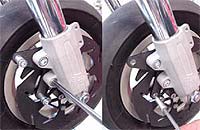
Put the right brake caliper without brake pads on the right brake holder and moun-on the screws with spacers. Secure the screws with glue and tighten them with properly adjusted torque wrench (9,5 Nm). Watch out for the brake shaft 312.038.00 in the caliper! |
 |
Re-fit the brake pads and brake pad springs into the calipers and secure them with screws. |
 |
Mount the new brake cable with adapter on. Follow the instructions below: |
 |
2. Pull the brake cable through the cable retainer – the shorter end of the cable goes to left brake caliper, the longer one to the right. |
 |
3. Set the lifter lever into the position so the wheel can freely turn. Tighten the cable retainer to secure the brake cable. |
up
|
Dismantle the front lining. Loosen the cable retainer and dismantle the brake cable. |
|
Unscrew the screw 312.018.00 and remove the brake pads and the brake pad spring from the calliper. |
|
Loosen the nut M10 and pull out the front wheel axle. Then pull the wheel out from the brake caliper in the direction of front fork. |
|
Remove the brake caliper from the brake holder. |
 |
Mount-on the kit brake caliper without brake pads and the pads spring (watch out for the brake shaft 312.038.00 in the caliper!). |
|
Re-mount the wheel on the front fork and tighten the wheel axle nuts (torque 35 Nm). |
|
Mount the new brake cable on. Follow the instructions in the Service manual to carry out the brake adjusting (chapter – Basic brake adjusting). |
up
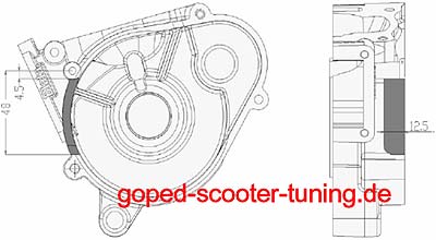 |
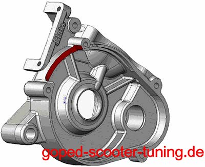
Remove material from the right part of the cylinder block according to diagram, cut out paper model 1 and use the model for dimension verification. |
 |
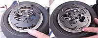
Adjust clearance between rotor and ignition coil according to the left scheme. |
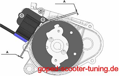 |
Keep the minimum clearance at value 0,25 to 0,3 mm to avoid rotor damage. |
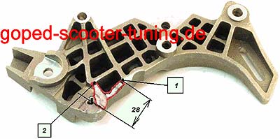 |
Side frame carrier modification to fit victory kit ignition coil only at the Origami Minibikes. |
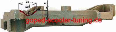 |
Cut material in 9 mm depth |
up

![]()